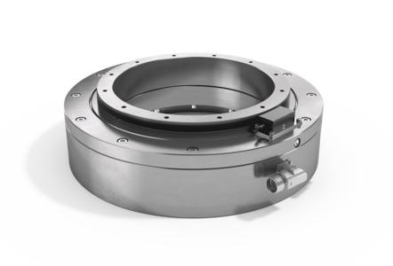
Close
Close

Country/region and language selection

Bearing assembly with Torque-Motor
Type LTD

Product image Bearing assembly with Torque-Motor Type LTD

5% discount
on your first online order!

Description

Bearing assemblies with direct drive are suitable for applications where high performance and low space requirements are important criteria. The integration of the drive into the bearing housing means that wear-prone assemblies for transmitting drive power, such as toothed belts, shafts or chains, can be dispensed with. This reduces the required drive energy and also benefits more accurate positioning.

Properties - Evaluation

Accuracy
Speed
Ø-Range
Price

Technical data

Material

C45N (optionally aluminium)

Operating temperature

-10 °C to +80 °C

Mounting position

Any

Lubricant

With bearing grease via grease nipple

Options

Absolute measuring system, axial cable outlet, control units incl. cables, water-cooling

Technical advice


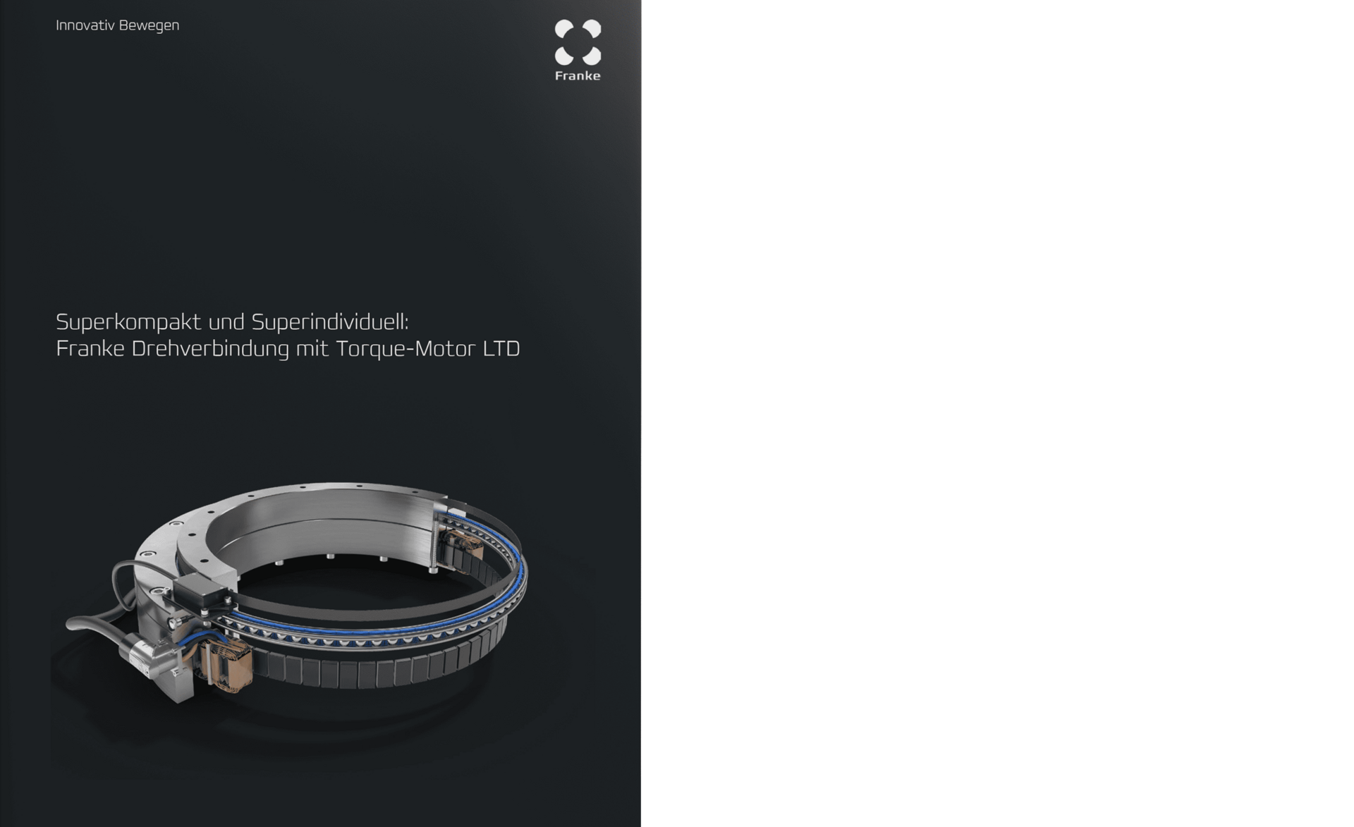
Super compact and super individual: Franke direct drive with torque motor LTD

Basic-Data

  • Housing steel or aluminium
  • KKØ: 100 - 1800 mm
  • Incremental measuring systems
  • Absolute measuring systems

The advantages

  • Compact design
  • Large centre clearance
  • Free choice of components
  • Four standard sizes from stock
  • Customised solutions

Function & benefits:

kompakt

Compact

dynamisch

Dynamic

energieeffizient

Energy efficient

Compact design, large centre clearance

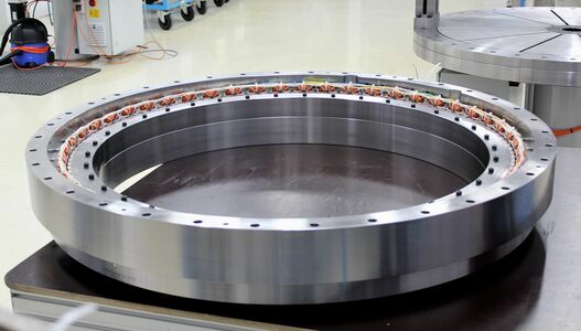
Franke bearing assemblies with integrated direct drive (torque motor) are characterized by high dynamics, maximum energy efficiency and a compact installation space combined with center-free design. 


Durchmesser Direktantriebe Torque

Available diameters

Franke bearings with direct drive are available in diameters from 100 mm to 1,800 mm.


Data tables

Compare data and calculate load cases
Technical Drawing LTD0100
LTD0100 MyFranke
Name ΚΚØ
mm
Load ratings
kN
Torque
Nm
Power
A
Speed
1/min.
Weight
kg
CAD-Download
Calculate loads
C0a C0r Ca Cr MNom MPeak INom IPeak nmax
LTD-0100 100 46 22 17 14 4,5 16 1,8 7 2140 8,0

Register now to get
access to MyFranke.

Power Graphs
Diagram Power Graphs LTD0100
Technical Drawing LTD0215
LTD0215 MyFranke
Name ΚΚØ
mm
Load ratings
kN
Torque
Nm
Power
A
Speed
1/min.
Weight
kg
CAD-Download
Calculate loads
C0a C0r Ca Cr MNom MPeak INom IPeak nmax
LTD-0215 215 128 60 26 22 26,4 105 3,1 12,8 640 21,0

Register now to get
access to MyFranke.

Power Graphs
Diagram Power Graphs LTD0215
Technical Drawing LTD0320
LTD0320 MyFranke
Name ΚΚØ
mm
Load ratings
kN
Torque
Nm
Power
A
Speed
1/min.
Weight
kg
CAD-Download
Calculate loads
C0a C0r Ca Cr MNom MPeak INom IPeak nmax
LTD-0320 320 382 180 45 39 77 329 4,3 21,6 300 44,0

Register now to get
access to MyFranke.

Power Graphs
Diagram Power Graphs LTD0320
Technical Drawing LTD0385
LTD0385 MyFranke
Name ΚΚØ
mm
Load ratings
kN
Torque
Nm
Power
A
Speed
1/min.
Weight
kg
CAD-Download
Calculate loads
C0a C0r Ca Cr MNom MPeak INom IPeak nmax
LTD-0385 385 458 216 48 41 118 522 4,3 21,7 193 57,0

Register now to get
access to MyFranke.

Power comparisonLTD-0100LTD-0215LTD-0320LTD-0385

Nominal Data (free air convection)

Nominal Torque TNomAC Nm 4,5 26,4 77 118
Nominal Current INomAC Arms 1,8 3,1 4,3 4,3
Nominal Speed nNomACLk rpm 2140 640 299 193
Nominal Power NomAC W 1005 1770 2409 2386
Winding Losses1 PVDAC W 54 131 230 309
Total Losses2 PDAC W 96 179 295 357
Holding Torque THAC Nm 3,2 18,7 54 83
Holding Current IHAC Arms 1,2 2,2 3 3
 

Peak Data

Peak Torque TPeak Nm 16 105 329 522
Peak Current IPeak Arms 7 12,8 21,6 21,7
Speed at Peak Torque nPeak rpm 1130 320 126 74
Peak Power PPeak W 1897 3526 4343 4049
Winding Losses1 PPeak W 863 2236 5886 7876
Total Losses2 PDPeak W 877 2253 5904 7889
 
Power Data
Torque Constant kt Nm/Arms 2,549 8,51 18,037 27,449
    Vrms/(rad/s) 1,577 5,2 11,094 16,694
BEMF Constant (Phase - Phase) ke Vrms/(rpm) 0,165 0,545 1,162 1,748
Motor Constant km Nm/vW 0,459 1,973 4,483 6,25
Idle Speed nidle rpm 2390 727 340 226
max. Speed (Fieldweaking) nmax rpm - - - -
max. Frequency (Idle/Fieldweaking) fmax Hz 398 254 159 124
DC Bus Voltage UDC VDC 560 560 560 560
Ø Resistance per Phase (winding only) RPh20 Ω 4,419 3,457 3,206 4,235
Ø Inductance per Phase (winding only) LPh mH 21,727 19,532 21,071 28,049
electr. Time Constant t=L/R Tel ms 4,92 5,65 6,57 6,62
Number of Polepairs n   10 21 28 33
Winding Connection     Star Star Star Star
 
Measuring System
Measuring Method incremental
Reference mark single coded
Measuring principle inductive
Interface 1 Vss
Cable length 1 m
Grating period 1000 µm
Line count 256 640 938 1200
Interpolation 10-fold
Number of signal periods 2560 6400 9380 12000
Position error per grating period ±11" ±4,5" ±3" ±2,5"
Grating period accuracy (±10µm arc length) ±51" ±20" ±14" ±11"
Max. scaning frequency 40 kHz
Voltage supply 4V to 7V DC
Electrical connection cable with M23, 12 pin male


Annotations

1 Winding Losses are referred to a Coil Temperature of 100°C.

2 The total Losses are made up of: Winding Losses; Stator Iron Losses; Rotor Losses;
Calculation of total Losses: Winding Losses + Stator Iron Losses (at speed X) + Rotor Losses (at speed X)

Ensure that your servo drive can handle the Nominal- and Peakcurrent of the Motor. An adjustment of the Speed and DC Bus Voltage can be done after consultation. The nominal data in this datasheet are based on an ambient/coolant temperature of 20°C.
The stated nominal Torques are without consideration of friction losses through Bearings or Sealings.

Because the exact duty type depends also on the thermal connection of the motor, the embedded thermal monitoring system has to be analysed and attented. However, attention has to be payed that the temperature sensors do not show the exact temperature of the winding and this could be up to 20 K higher due to thermal capacities. Despite an electrical insulation towards the winding, you are only allowed to connect the sensors to your controller by using a galvanic separation in between.